Rotating building/maintenance stand
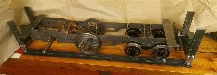
I have been building this stand to help with construction and maintenance of the 5" gauge locomotive which I am currently building. It has been designed “on the fly” with no drawings, and most decisions taken based on the materials I had in stock. Most components are assembled with set-screws to allow parts to be exchanged.
●
The base consists of two pieces of angle, set to 5” gauge so the loco can be rolled on and off (with one end of the stand removed). With different end-assemblies, it will also serve as a track for carrying the finished loco in the car.
Each end has a pair of uprights bolted to the base and having a series of regularly spaced holes to allow a cross-plate to be fitted at various heights. A second, sliding plate is supported from the first plate on 12mm studding and slotted at the ends to slide on the uprights. This provides for finer height adjustment. A plain bearing block is bolted to the sliding plate.
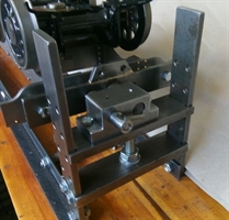
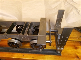
These pictures show the right-hand end. The bearing block at this end has a second hole for a sleeve to carry a bolt to lock the rotating plate in one of six positions. Two of the holes for locking the rotating plate can just be seen above the fulcrum block. The locomotive frames can be seen rotated through 180 degrees.
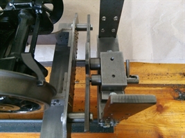
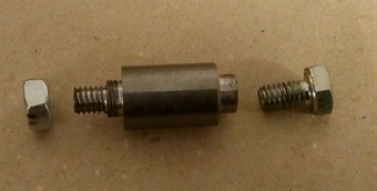
To attach the loco to the swivelling plates, there are four “dummy buffers”, two of which can be seen in the right-hand image above, and in its component parts (right). The left-hand end has a short length of 5/16” x 40 thread to match the hole in the buffer-beam, and an extended length of M6 to take a nut. The right-hand end has a 5/16” spigot to fit in the swivel plate, and is tapped M6 for a set-screw to secure it.
I had originally thought of fitting the bolt mechanism as a press fit, or with Loctite, but in order to allow easier modification in future, in common with the rest of the design, it is a sliding fit and secured by a grub screw.
All material came from stock except the 12mm studding and nuts.
All material came from stock except the 12mm studding and nuts.

Copyright © 2019-2026 Bournemouth & District Society of Model Engineers.